Sistema di controllo di piccole dimensioni
SAFELINE VARIO
SAFELINE VARIO è un sistema di sicurezza multifunzionale, modulare e configurabile, progettato per l'uso in macchinari e impianti industriali. È composto da un modulo centrale e da una selezione di moduli funzionali e di bus di campo che possono essere combinati a seconda delle esigenze. È disponibile una varietà di ingressi digitali e analogici sicuri, nonché di uscite a semiconduttore e a contatto. I moduli possono essere facilmente configurati e adattati utilizzando SL VARIO Designer. SAFELINE VARIO soddisfa i requisiti di DIN EN ISO 13849-1 fino al Performance Level e.
.png)


General Features


![]()
![]()
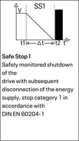
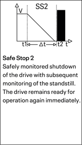
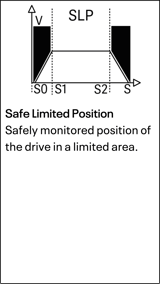
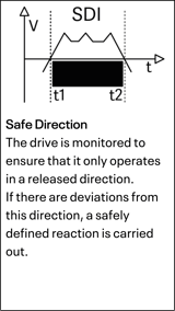
Safety Features
Evaluation

Fieldbus Connectivity

Electronic requirements
| Module | ZMV | ZMVK |
| Operating voltage at A1, A2 | 24V DC, -15% + 10% | 24V DC, -15% + 10% |
| Onput current via A1 | ≤ 4A / internal fuse: 6A | ≤ 4A / internal fuse: 6A |
| Power cosumption in W | 2,9 | 7,7 |
| Weight in gram | 350 | 570 |
| Module | ZMVA | ZMVD |
| Operating voltage at A1, A2 | 24V DC, -15% + 10% | 24V DC, -15% + 10% |
| Input current via A1 | ≤ 4A / internal fuse: 6A | ≤ 4A / internal fuse: 6A |
| Power cosumption in W | 3,0 | 3,0 |
| Weight in gram | 450 | 450 |
Semiconductor Outputs
| Module | ZMV | ZMVK |
| Outputs PL | IO1–IO4 PLe | O1–O6 PLe |
| Type of Output | ||
| Switching and continuous current Ω/L | 0,1 A | 1 A |
| Total switching and continuous current Ω/L | 0,4 A | 3 A |
| Min. switching current Ω/L | 1 mA | 1 mA |
Contact Outputs
| Module | ZMV, ZMVD | ZMVK |
| Outputs | K1, K2 | K3 – K6 |
| Output execution Performance level: e | ||
| Minimum switching current | 10 mA | 10 mA |
| Breaking capacity according to DIN EN 60947-4-1/ EN 60947-5-1 | DC13: 24 V / 2 A AC15: 250 V / 3 A |
DC1: 24 V / 6 A DC13: 24 V / 4 A / 0,1 Hz |
| Sum of switching and continuous currents | K1, K2: ≤ 6A | K3, K4: ≤ 6A, K5, K6: ≤ 6A |
| Lifetime at DC13: 24V/ 1A | 1,5 x 10^5 | 1 x 10^5 |
| Lifetime at DC13: 24V/ 4A | 10^4 | 4 x 10^4 |
| Lifetime at DC13: 24V/ 1A | 1,5 x 10^5 | 1 x 10^5 |
| Mechanical lifetime | >50x10^6 | >10^7 |
| Maximum switching cycles with DC13: 4A | 360 Cycles/h | 360 Cycles/h |
| Maximum switching cycles with AC15: 3A | 360 Cycles/h | - |
| Contact fuse protection | 6A inert | 6A inert |
| Short-circuit resistance: | 200A/BG 800A/6A gG |
1000A SCPD 6A |
| Rated insulation voltage | 250V AC | - |
| Surge voltage resistance Pollution degree 2 Environment | 4KV | - |
| Response / release time typical | 15 ms/ 12 ms | 10ms/ 3 ms |
Environmental Data
| Operating temperature | -10°C bis +55°C |
| Storage Temperature | -40°C bis +85°C |
| Vibration (in 3 levels) | sin 10 bis 55 Hz, 0,35 mm (0.014 in), 10 Zyklen, 1 Oktave/min. |
| Shock resistance of the output relays (in 3 levels) | ≤5 g, 11 ms |
| Connection cross-section | 0,25 - 2,5mm2 with ferrules |
| Terminals | Spring-loaded terminals, pluggable |
| Connection Fuse | Only 60/75°C Copper |
| Casing material | Polyamid PA non-reinforced |
| Protection Class | Casing and Terminals: IP20, Installation Site: minimal IP 54 |
| Voltage at the inputs for safety matsn |
Safety mat activated: 24 V
Safety mat nominal: 11,5 V Safety mat undamped: 9,5 bis 14 V |
| Response time for safety mats | < 25ms |
| Voltage at the inputs | 24V DC -15%, ≤10% Ripple |
| Current consumption of the inputs | Max. 4.0mA |
| Input voltage at terminal P at DSV, DRV, SIV, IOV and NIV | 24 V DC (-15/+10%) |
| Input current at terminal P at DSV, DRV, SIV, IOV and NIV | < 4 A |
| Input frequency at I9 - I12 on the central module | ≤ 500Hz via 2 sensors e.g. proximity switch |
| Input frequency at I9 - I16 on the central module | ≤ 50KHz for HTL signals via incremental measuring system |
| Input Frequency at DNSL-DSV |
≤ 500KHz sin/cos 1Vpp or TTL signals
|
| Input frequency at DNSL-DRV | ≤ 1200Hz sin/cos 1 to 10Vpp |
| Input frequency at DNSL-DRV | ≤ 1200Hz sin/cos 1 to 10Vpp |
| Accuracy of analogue Inputs | ±3% of full scale over the temperature range -10 to +60°C |
| Input impedance of the analogue inputs | At 4-20mA approx. 500Ω, at 0-10V > 5KΩ |
Drawing ZMV

Drawing ZMVK (Extension)

Drawing ZMVD (Extension DS1)

Drawing ZMVD (Extension DS2)

Safety-relevant Parameters according to DIN ISO 13849-1
| Modul | MTTFd [a] | Kat./PL | PFHd |
| DNSL-ZMV | 98 | 4/e | 2,4 x 10⁻⁸ |
| DNSL-ZMVK | 37 | 4/e | 7,7 x 10⁻⁸ |
| DNSL-ZMVD | 92 | 4/e | 2,7 x 10⁻⁸ |
| DNSL-ZMVD2 | 86 | 4/e | 3,0 x 10⁻⁸ |
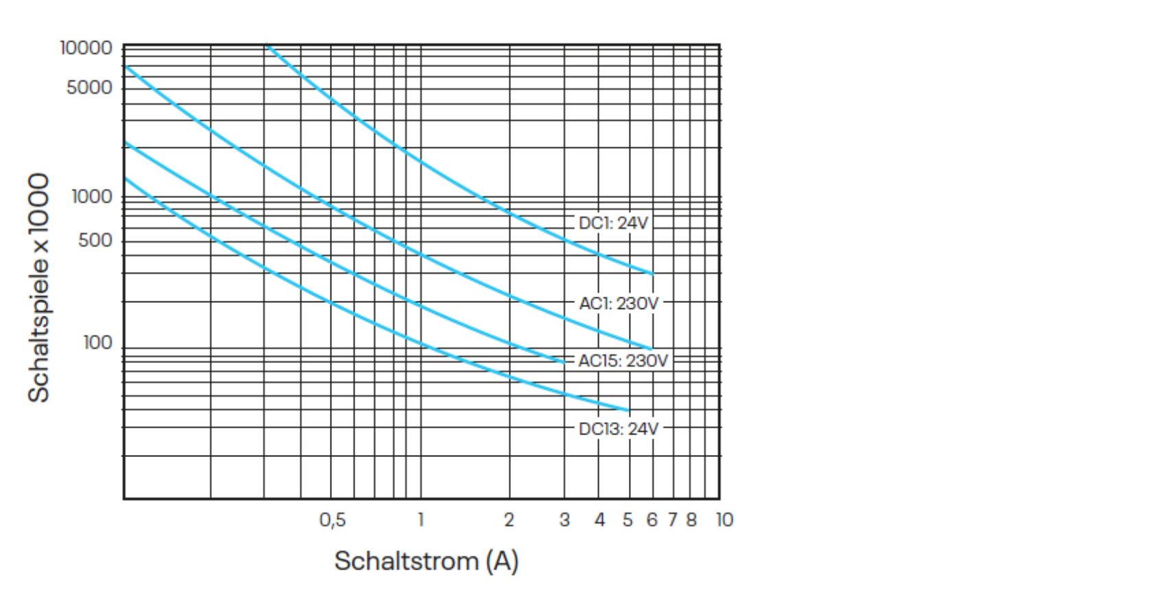
Contact Service Life
Electrical contact service life of the output contacts according to DIN EN 60947-5-1 Appendix C.3.
DNSL-ZMV, -ZMVK, ZMVD K1 and K2
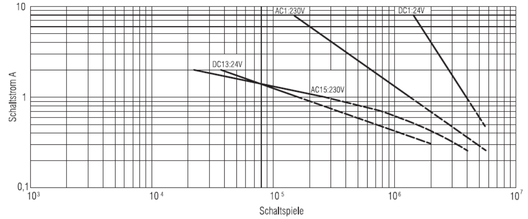
DNSL-ZMVK K3 until K6