Small control system
SAFELINE VARIO
SAFELINE VARIO is a multifunctional, modular and configurable safety system designed for use in machinery and industrial facilities. It consists of a central module and a selection of function and fieldbus modules that can be combined as required. A variety of safe digital and analogue inputs, as well as semiconductor and contact outputs, are available. The modules can be easily configured and adapted using SL VARIO Designer. SAFELINE VARIO meets the requirements of DIN EN ISO 13849-1 up to Performance Level e.
.png)


General Features


![]()
![]()
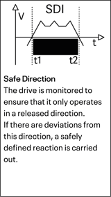
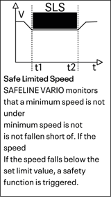
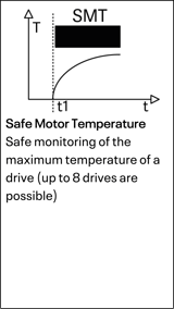
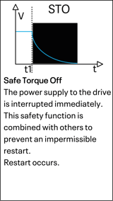
Safety Features
Evaluation

Fieldbus Connectivity

Electronic requirements
| Module | ZMV | ZMVK |
| Operating voltage at A1, A2 | 24V DC, -15% + 10% | 24V DC, -15% + 10% |
| Onput current via A1 | ≤ 4A / internal fuse: 6A | ≤ 4A / internal fuse: 6A |
| Power cosumption in W | 2,9 | 7,7 |
| Weight in gram | 350 | 570 |
| Module | ZMVA | ZMVD |
| Operating voltage at A1, A2 | 24V DC, -15% + 10% | 24V DC, -15% + 10% |
| Input current via A1 | ≤ 4A / internal fuse: 6A | ≤ 4A / internal fuse: 6A |
| Power cosumption in W | 3,0 | 3,0 |
| Weight in gram | 450 | 450 |
Semiconductor Outputs
| Module | ZMV | ZMVK |
| Outputs PL | IO1–IO4 PLe | O1–O6 PLe |
| Type of Output | ||
| Switching and continuous current Ω/L | 0,1 A | 1 A |
| Total switching and continuous current Ω/L | 0,4 A | 3 A |
| Min. switching current Ω/L | 1 mA | 1 mA |
Contact Outputs
| Module | ZMV, ZMVD | ZMVK |
| Outputs | K1, K2 | K3 – K6 |
| Output execution Performance level: e | ||
| Minimum switching current | 10 mA | 10 mA |
| Breaking capacity according to DIN EN 60947-4-1/ EN 60947-5-1 | DC13: 24 V / 2 A AC15: 250 V / 3 A |
DC1: 24 V / 6 A DC13: 24 V / 4 A / 0,1 Hz |
| Sum of switching and continuous currents | K1, K2: ≤ 6A | K3, K4: ≤ 6A, K5, K6: ≤ 6A |
| Lifetime at DC13: 24V/ 1A | 1,5 x 10^5 | 1 x 10^5 |
| Lifetime at DC13: 24V/ 4A | 10^4 | 4 x 10^4 |
| Lifetime at DC13: 24V/ 1A | 1,5 x 10^5 | 1 x 10^5 |
| Mechanical lifetime | >50x10^6 | >10^7 |
| Maximum switching cycles with DC13: 4A | 360 Cycles/h | 360 Cycles/h |
| Maximum switching cycles with AC15: 3A | 360 Cycles/h | - |
| Contact fuse protection | 6A inert | 6A inert |
| Short-circuit resistance: | 200A/BG 800A/6A gG |
1000A SCPD 6A |
| Rated insulation voltage | 250V AC | - |
| Surge voltage resistance Pollution degree 2 Environment | 4KV | - |
| Response / release time typical | 15 ms/ 12 ms | 10ms/ 3 ms |
Environmental Data
| Operating temperature | -10°C bis +55°C |
| Storage Temperature | -40°C bis +85°C |
| Vibration (in 3 levels) | sin 10 bis 55 Hz, 0,35 mm (0.014 in), 10 Zyklen, 1 Oktave/min. |
| Shock resistance of the output relays (in 3 levels) | ≤5 g, 11 ms |
| Connection cross-section | 0,25 - 2,5mm2 with ferrules |
| Terminals | Spring-loaded terminals, pluggable |
| Connection Fuse | Only 60/75°C Copper |
| Casing material | Polyamid PA non-reinforced |
| Protection Class | Casing and Terminals: IP20, Installation Site: minimal IP 54 |
| Voltage at the inputs for safety matsn |
Safety mat activated: 24 V
Safety mat nominal: 11,5 V Safety mat undamped: 9,5 bis 14 V |
| Response time for safety mats | < 25ms |
| Voltage at the inputs | 24V DC -15%, ≤10% Ripple |
| Current consumption of the inputs | Max. 4.0mA |
| Input voltage at terminal P at DSV, DRV, SIV, IOV and NIV | 24 V DC (-15/+10%) |
| Input current at terminal P at DSV, DRV, SIV, IOV and NIV | < 4 A |
| Input frequency at I9 - I12 on the central module | ≤ 500Hz via 2 sensors e.g. proximity switch |
| Input frequency at I9 - I16 on the central module | ≤ 50KHz for HTL signals via incremental measuring system |
| Input Frequency at DNSL-DSV |
≤ 500KHz sin/cos 1Vpp or TTL signals
|
| Input frequency at DNSL-DRV | ≤ 1200Hz sin/cos 1 to 10Vpp |
| Input frequency at DNSL-DRV | ≤ 1200Hz sin/cos 1 to 10Vpp |
| Accuracy of analogue Inputs | ±3% of full scale over the temperature range -10 to +60°C |
| Input impedance of the analogue inputs | At 4-20mA approx. 500Ω, at 0-10V > 5KΩ |
Drawing ZMV

Drawing ZMVK (Extension)

Drawing ZMVD (Extension DS1)

Drawing ZMVD (Extension DS2)

Safety-relevant Parameters according to DIN ISO 13849-1
| Modul | MTTFd [a] | Kat./PL | PFHd |
| DNSL-ZMV | 98 | 4/e | 2,4 x 10⁻⁸ |
| DNSL-ZMVK | 37 | 4/e | 7,7 x 10⁻⁸ |
| DNSL-ZMVD | 92 | 4/e | 2,7 x 10⁻⁸ |
| DNSL-ZMVD2 | 86 | 4/e | 3,0 x 10⁻⁸ |
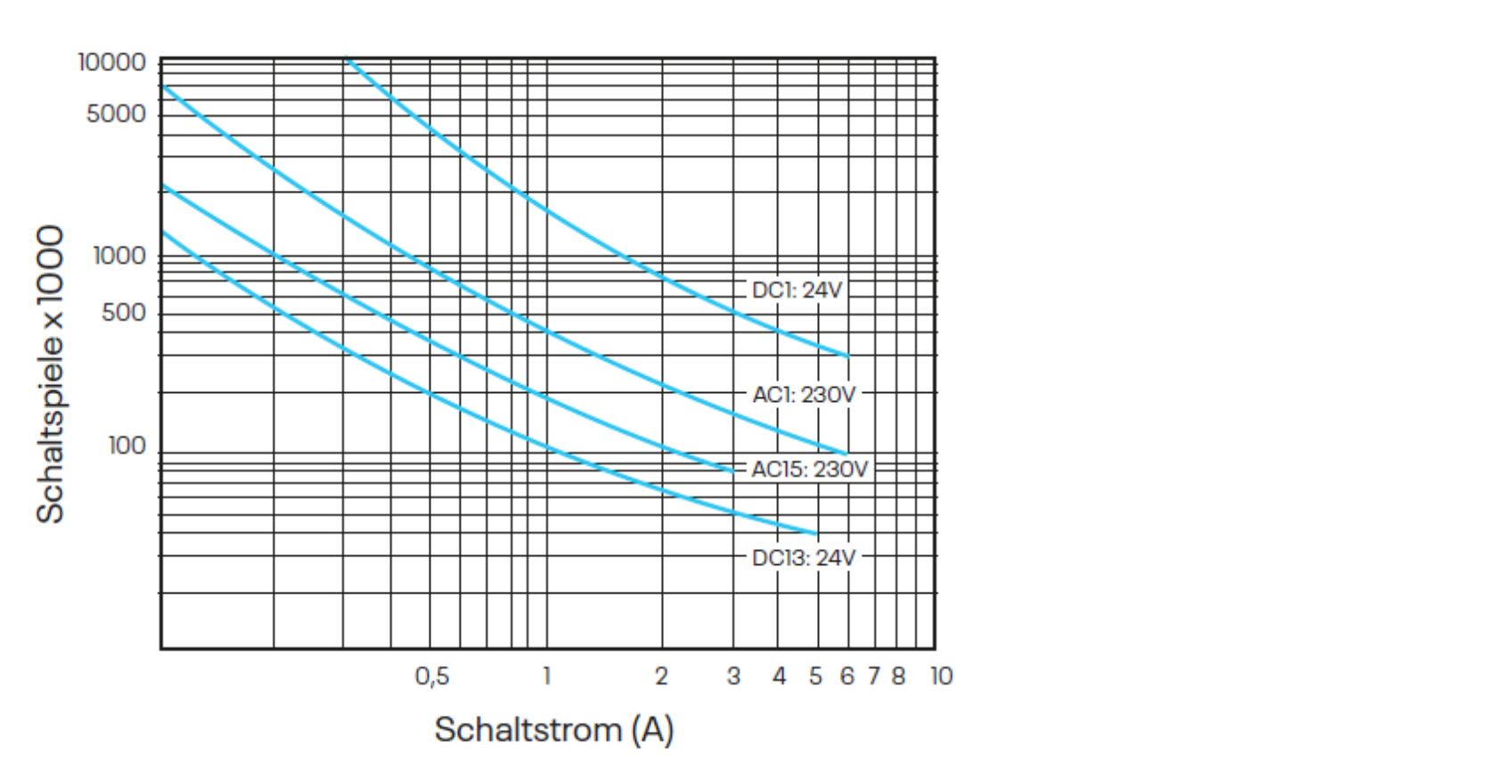
Contact Service Life
Electrical contact service life of the output contacts according to DIN EN 60947-5-1 Appendix C.3.
DNSL-ZMV, -ZMVK, ZMVD K1 and K2
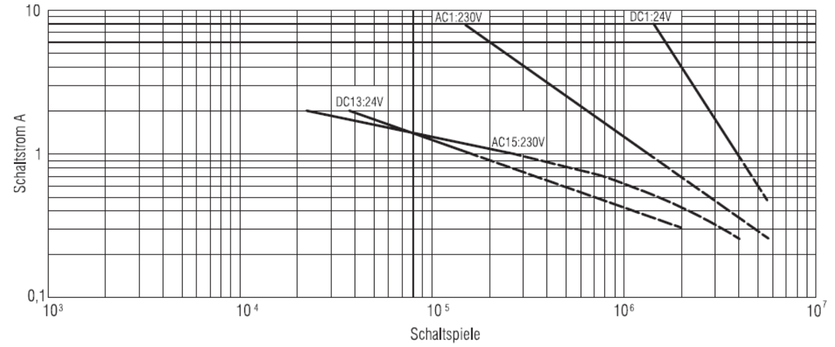
DNSL-ZMVK K3 until K6